Data: UPD 17th November 2023
Attwood 3830 Marine Lighting PDF Instructions (Updated: Friday 17th of November 2023 08:04:19 PM)
Rating: 4.9 (rated by 60 users)
Compatible devices: 5100 Series, Pulsar 5040, 6340 Series, 5300 Series, 7800 Series, 66318, 911339, 6316.
Recommended Documentation:
Text Version of Attwood 3830 Marine Lighting Manual (Summary of Contents)
(Ocr-Read of Document's Main Page, UPD: 17 November 2023)
2-Mile Vertical Sidelights
Models 3830, 3834, 3838, 3831, 3835 and 3839
SAVE THESE INSTRUCTIONS
Form Number 69393 Rev. B 03-10
3
®
©2003 Attwood Corporation
1016 N. Monroe Street, Lowell, MI 49331-0260 www.attwoodmarine.com
12-Volt 24-Volt
Models Models Description
3830 3831 Black Base, Red/Green Vertical Sidelight Pair
3834 3835 White Base, Red/Green Vertical Sidelight Pair
3838 3839 S.S. Base, Red/Green Vertical Sidelight Pair
FEATURES
These Attwood Stainless Steel Vertical Sidelights provide 2 Nautical
Mile visibility and are designed for boats up to 20 meters/65.6 feet.
The housing is corrosion-proof and the base gasket forms a seal
between the lens and deck for easy, water-resistant installation.
Lights meet USCG CFR 183.810, ABYC A-16 requirements, and all
applicable standards as tested by Immana Labs, 7/28/2003. Lights
use 8-watt festoon lamp, Attwood Part No. #9230 (13-volt) or #910409
(24-volt). See chart above for voltage.
REQUIRED FOR INSTALLATION
• Phillips screwdriver
• Cordless drill; 7/64" (#32 drill) and 3/8" (3 and 10mm) bits
• Three #6 pan head stainless steel tapping screws (not included)
• Marine-grade non-silicone sealant
• 16-gauge wire and waterproof crimp connectors
INSTALLATION LOCATION
Before drilling mounting holes, position sidelights on a surface
of the gunwale or deck where you are certain that sidelights:
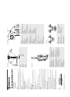
• Are equal distance from the bow (Figure 1)
• Shine straight ahead
• Shine within 5° of horizontal when the boat is floating
• The light beam is not obstructed
Place lights with the red lens on the port (left) and green lens on
the starboard (right). Be sure there are no obstructions at the front
or side within the light’s arc of visibility (112.5 degrees each side).
INSTALLATION
1. To access light base mounting holes, remove exterior screw and
stainless steel or plastic lens helmet. (Figure 2)
2. Remove lens screw and colored lens. Save screws, helmet, and
lens for reinstallation.
3. Place light in position as shown in Figure 1.
4. Hold base with “FRONT” arrow pointing forward.
Important: Before drilling, be sure that light will shine straight ahead
and within 5° of horizontal when boat is floating.
5. Use base as a template to mark location of three mounting holes
and a center hole for wire access.
CAUTION
Position wire access hole carefully, especially on aluminum boats,
so that wires do not contact the hull.
6. Drill 3/8" (10mm) diameter hole for wire access and three 7/64"
(3mm) diameter holes for mounting screws. (Figure 2).
7. Bring one 16-gauge (+) and one (-) wire up through access hole.
DO NOT connect these wires to power until you read FINAL
WIRING INSTRUCTIONS (Figure 3)
8. Connect wires using waterproof crimp connectors.
9. Fasten light to deck with three #6 stainless steel screws. DO NOT
OVERTIGHTEN screws.
10. Replace lens over base. Replace lens screw.
11. Replace helmet over lens. Replace helmet screw.
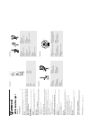
FINAL WIRING INSTRUCTIONS
Use ONLY the rated voltage (see chart above). All positive wires
must be protected by a 1-amp fuse. Higher voltage or failure to make
proper wire and fuse connections will void the product warranty. Use
crimp type marine-grade connectors with suitable insulation. Protect
all connections with suitable materials.
Figure 2
F
R
O
N
T
3/8" (10mm)
dia. Hole
Base
Lens
Helmet
Figure 1
Green
(Starboard)
Red
(Port)
1. Neatly thread wires to the switch, avoiding areas where abrasion
or snagging may occur.
2. Use switch (Attwood #14386 or equivalent) that allows two-position
ON/OFF/ON operation — one for running lights, and one for anchor
lights. Attach wires with crimp-on butt joint connectors. Test lights
for proper operation.
MAINTENANCE
To replace lamp: Remove the helmet and lens (Figure 2). Use small
slotted screwdriver to pry old lamp out of terminals. Replace with the
proper festoon-base lamp: Attwood #9230 (12-volt), or #910409
(24-volt). Replace lens, helmet, and retaining screws.
ATTWOOD LIMITED WARRANTY
This product carries the standard Attwood one-year warranty.
See Product Catalog or www.attwoodmarine.com for details.
Figure 3
(pos)
(neg)(pos)
Red PortGreen Starboard
Fuse
3-Way Switch
Recommended:
STP1, TokenLink 3C359B, UT32S402 - LCD Direct View TV, 8058869
Grand Slam 900, UBL-x180, 3830, MS-2000(M) DISTRESS MARKER LIGHT (MILITARY), MSR0640, FR380
-
© 2008 Attwood Corporation1016 N. Monroe Street, Lowell, MI 49331-0260 www.attwoodmarine.com WARNINGRemove vessel from water before using any 120-volt power tools.REQUIRED FOR INSTALLATION• 3/4" (19mm) diameter hole saw or drill bit • 18-gauge wire: white (positive) and black (ne ...
Model & Doc Type: 6316 2
-
FEATURESAttwood 3-mile (4.8 km) Anchor/Masthead Lights consist of anodizedaluminum poles with lightweight heads. Horizontal and vertical basesallow light pole to be adjusted and locked within a 180° arc.Lights provide a 3-mile, 225° forward running light and 2-mile all-roundanchor light. F ...
Model & Doc Type: 7200 Series 2
-
REQUIRED FOR INSTALLATIONPhillips screwdriver• Drill and bits: 3/16″ for wire clearance hole• Pilot drill for mounting screws• Two #4 Stainless Steel screws (not included)• LOCATIONLights can be positioned in any exterior or interior location. Lights are 1. intended for surface mount ...
Model & Doc Type: 6350 Series 2
-
2-Mile LED Transom LightModel 6556SAVE THESE INSTRUCTIONSForm Number 69437 Rev. A 08-04 WARNING Read all instructions carefully before installing and using this product. To prevent personal injury, disconnect the power source when installing or servicing this product. Always remove the b ...
Model & Doc Type: 6556 2
Operating Impressions, Questions and Answers: