Data: UPD 19th October 2023
Supermicro X10SAE Motherboard PDF Quick Reference Manual (Updated: Thursday 19th of October 2023 11:48:42 AM)
Rating: 4.5 (rated by 29 users)
Compatible devices: PDSM4, C7H270-CG-ML, X11DPT-BH, A2SAP-H, X11DDW-L/NT, X10SDD-F, X10DRD-L, X6DAL-G.
Recommended Documentation:
Text Version of Supermicro X10SAE Motherboard Manual (Summary of Contents)
(Ocr-Read of Document's Main Page, UPD: 19 October 2023)
S
UPERMICR
R
ContaCt InformatIon
• www.supermicro.com (Email: [email protected])
• Manuals: http://www.supermicro.com/support/manuals
• Drivers & Utilities: ftp://ftp.supermicro.com
• Safety: http://www.supermicro.com/about/policies/safety_information.cfm
PaCkage Contents
(Applies to individual-pack only)
X10SAE
QuICk referenCe guIde
• One (1) Supermicro Motherboard
• Eight (8) SATA Cables
• One (1) I/O Shield
• One (1) Quick Reference Guide
MNL-1479-QRG
© 2012 Supermicro Computer Inc. All rights reserved. Reproduction of this document whether in part or in whole is strictly prohibited without Supermicro's written
consent. All Trademarks are property of their respective entities. All information provided is deemed accurate at the time of printing; however, it is not guaranteed.
MNL-1479-QRG
1394 CODE
JLED1
JVR2
JPL1
JBR1
JPME1
JPL2
JPAC1
JPME2
JWD1
JPI1
JVR1
JBT1
LV33
JSTBY1
JSD1
T-SGPIO1
X10SAE
BIOS
LICENSE
JTPM1
JPW2
I-SATA1
I-SATA2
I-SATA3
I-SATA5
I-SATA4
J1394_2
J1394_1
JL1
JHD_AC1
JWOR1
JSPDIF_OUT
JI2C1
JI2C2
JPW1
MAC CODE
BAR CODE
LED1
SP1
FAN3
FAN2
FAN5
FAN1FAN4
JD1
SLOT5 PCI-E 2.0 X1
SLOT3 PCI-E 2.0 X1
SLOT1 PCI 33MHz
SLOT2 PCI 33MHz
USB 14/15(3.0)
USB12/13(3.0)
USB8/9
USB 2/3
LAN2 LAN1
HDMI/DP
KB/MOUSE
CPU
/CPU FAN
USB 0/1
AUDIO FP
DIMMB1
DIMMB2
HD AUDIO
USB4/5
USB6/7
DIMMA1
DIMMA2
JF1
Always populate blue sockets first;
Unbuffered ECC/Non-ECC DDR3 DIMM required
SLOT4 PCI-E 3.0 X8 (IN X16)
SLOT6 PCI-E 3.0 X16
SLOT7 PCI-E 2.0 X1
COM2
COM1
VGA/DVI
USB10/11(3.0)
T-SGPIO2
A-SATA0
A-SATA1
BIOS
Intel PCH
I-SATA0
BATTERY
The X10SAE supports up to 32GB of Unbuffered (UDIMM) DDR3 ECC/non-
ECC 1600/1333/1066 MHz in 4 memory slots. Populating these DIMM modules
with a pair of memory modules of the same type and same size will result in
interleaved memory, which will improve memory performance.
Note: For memory optimization, use only DIMM modules that have been validated by Supermicro.
For the latest memory updates, please refer to our website at http://www.supermicro.com/
products/motherboard.
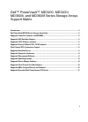
Motherboard Layout and Features
Jumpers, Connectors and LED Indicators
Note: Graphics shown in this quick reference guide are for illustration only. Your components may or may not look exactly the same as drawings shown in this guide.
Back Panel IO Connectors
Memory Support
Note: Refer to Chapter 2 of the User Manual for detailed information on memory support and CPU/
motherboard installation instructions.
Note: Refer to Chapter 2 of the User Manual for detailed information on jumpers, connectors, and LED indicators.
= mounting hole
A
B
C
D
E
F
G
H
I
DIMMB2
DIMMA2
DIMMB1
DIMMA1
Note: Up to 32GB of memory are supported. See chapter 2 of the User Manual for
complete memory population information.
Towards the CPU
Jumpers
Connectors
LED Indicators
DIMM Memory Installation
Memory Population Guidelines
When installing memory modules, the DIMM slots should be populated in the fol-
lowing order: DIMMA2, DIMMB2, then DIMMA1, DIMMB1.
• Always use DDR3 DIMM modules of the same size, type and speed.
• Mixed DIMM speeds can be installed. However, all DIMMs will run at the speed
of the slowest DIMM.
Recommended Population (Balanced)
DIMMA2 DIMMB2 DIMMA1 DIMMB1 Total System Memory
1GB 1GB 2GB
1GB 1GB 1GB 1GB 4GB
2GB 2GB 4GB
2GB 2GB 2GB 2GB 8GB
4GB 4GB 8GB
4GB 4GB 4GB 4GB 16GB
8GB 8GB 16GB
8GB 8GB 8GB 8GB 32GB
JBT1 CMOS Clear (See Chpt. 2)
JI
2
C1/JI
2
C2 SMB to PCI Slots Off (Disabled)
JHD_AC1 High Denition (HD) Audio Enable Pins 1-2 (Enabled)
JPAC1 Front Panel Audio Enable Pins 1-2 (Enabled)
JPI1 1394_1/1394_2 Enable Pins 1-2 (Enabled)
JPL1/JPL2 LAN1/LAN2 Enable Pins 1-2 (Enabled)
JWD1 Watch Dog Enable Pins 2-3 (NMI)
1394_1/2 1394 Connectors 1/2
Audio FP Front Panel Audio Header
HD AUDIO High-Denition Audio Connectors (on the I/O back panel)
BATTERY Onboard Battery
COM1/COM2 COM1/COM2 Port Headers
Fan1~Fan5 System/CPU Fan Headers (Fan1: CPU Fan)
HDMI/DP Backplane HDMI(High-Denition Multimedia Interface)/DP Audio Port
JD1 Speaker/buzzer (Pins 3-4: Buzzer, Pins 1~4: External Speaker)
JF1 Front Panel Control Header
JL1 Chassis Intrusion Header
JLED1 Power LED Indicator Header
JPW1 24-pin ATX Main Power Connector (Required)
JPW2 +12V 8-pin CPU power Connector (Required)
JSD1 SATA DOM (Device_On_Module) Power Connector
JSPDIF_OUT Sony/Philips Digital Interface (SPDIF)_Out Header
JSTBY1 Standby Power Header
JTPM1 Trusted Platform Module/Port 80 Connector
JVR1/JVR2 PWM SMB programming headers 1/2(for debugging only)
JWOR1 Wake_On-Ring Header
KB/Mouse Keyboard/Mouse Connectors
LAN1/LAN2 Gigabit (RJ45) Ports (LAN1/2)
SP1 Internal Speaker/Buzzer
A-SATA0/A-SATA1 (ASMedia) Serial ATA (SATA 3.0) Ports 0/1 (6Gb/sec)
I-SATA0-I-SATA5 (Intel) Serial ATA (SATA 3.0) Ports 0-5 (6Gb/sec)
Slot 3/Slot 5/Slot 7 PCI-Express 2.0 x1 Slots
Slot 6 PCI-Express 3.0 x16 Slot (x8 if Slot 4 is used)
Slot 4 PCI-Express 3.0 x8 in x16 Slot
Slot 1, Slot 2 PCI 33MHz Slot (5V)
T-SGPIO 1/2 Serial_Link General Purpose I/O Connection Headers 1/2
USB 0/1, 2/3 Backpanel USB 2.0 Ports 0/1, 2/3
USB 10/11 Backpanel USB 3.0 Ports 10/11
USB 4/5, USB 6/7, USB 8/9 Front Panel Accessible USB 2.0 Headers 4/5, 6/7, 8/9
USB 3.0 12/13, 14/15 Front Panel Accessible USB 3.0 Headers 12/13, 14/15
VGA/DVI Backpanel VGA/DVI (Digital Video Interface) Port
LED1 Onboard Standby PWR LED Green: Solid on Power On
Front Panel Control (JF1)
CPU Installation
Power Button
OH/Fan Fail LED
1
NIC1 LED
Reset Button
2
HDD LED
Power LED
Reset
PWR
LED_Anode+
LED_Anode+
LED_Anode+
LED_Anode+
Ground
Ground
X
X
NIC2 LED
LED_Anode+
Backplane I/O Panel
A. USB 2.0 Port 0 G. Display/Port Connector N. SPDIF Out
B. USB 2.0 Port 1 H. USB 3.0 Port 10 O. Surround Out
C. Keyboard/Mouse I. USB 3.0 Port 11 P. Center/LFE Out
D. DVI Port J. Gb LAN Port 1 Q. Mic In
E. VGA Port K. USB 2.0 Port 2 R. Line Out
F. HDMI Port L. USB 2.0 Port 3 S. Line In
(N-S: HD Audio Jacks)
J
K
L
M
N
O
P
Q
R
HD Audio
S
Heatsink Installation
Heatsink
with Fan
Motherboard
Mounting Hole
Recommended:
MES-N, Accompli A002, T451A, IH-K241LS
LMX2531LQ1226E, D915GLVG, DQ43AP, LegenX 8, QEG-1, B75H2-M3
-
IQuick StartQuick StartThank you for purchasing the MSI® H170M PRO-VDH/ B150M PRO-VDH motherboard. This Quick Start section provides demonstration diagrams about how to install your computer. Some of the installations also provide video demonstrations. Please link to the URL to watch it with the we ...
Model & Doc Type: H170M PRO-VDH 132
-
935-852GM2-00085900512852GME-MGF ProSystem Board User’s ManualCarte Mère Manuel Pour UtilisateurSystem-Platine BenutzerhandbuchManual del Usuario de Placas BaseÐóêîâîäñòâî ÏîëüçîâàòåëÿÐóêîâîäñòâî ÏîëüçîâàòåëÿÐóêîâîäñòâî Ïîëüçîâà ...
Model & Doc Type: 852GME-MGF Pro 39
-
ENOverrideExtra HourModeDAY/PROG RUNTIMEOKHolidaysOFFamThuAUTOONCECONTEXT HOUR+1+2+307 / 02 / 2013ON1SelectOperating ManualQEG-1QEG-1SInstallation und MontageOperation and confi gurationSafety InstructionsQuick-start guide – 3 clicks to total control• To avoid injuries, the device ...
Model & Doc Type: QEG-1 2
-
ADL6012-EVALZ User GuideUG-1675One Technology Way • P. O. Box 9106 • Norwood, MA 02062-9106, U.S.A. • Te l: 781.329.4700 • Fax: 781.461.3113 • www.analog.com Evaluating the ADL6012 2 GHz to 67 GHz, 500 MHz Bandwidth, Envelope Detector PLEASE SEE THE LAST PAGE FOR AN IMPORTANT WARNING ...
Model & Doc Type: ADL6012-EVALZ 9
Operating Impressions, Questions and Answers: